Firewall Analyzer supports the following versions of various Cisco devices.
Cisco IOS Firewalls:
Cisco FWSM Catalyst Series:
Cisco PIX versions:
Cisco ASA:
5500 series
Cisco VPN Concentrators Series:
| Model Family | Model | Cisco IOS Software Version |
|---|---|---|
|
8xx |
c871, c876, c877,c878 |
12.4(4)T |
|
18xx |
c1841 |
12.3(14)T |
|
c1811, c1812 |
12.4(4)T |
|
|
c1801, c1802, c1803 |
12.4(4)T |
|
|
28xx |
c2801, c2851, c2821, c2811 |
12.3(14)T |
|
38xx |
c3845, c3825 |
12.3(14)T |
|
72xx |
7206VXR, 7204VXR |
12.3(14)T |
|
73xx |
CISCO7301 |
12.3(14)T |
To find out the version of your PIX firewall, Telnet to the PIX firewall and enter the show version command.
|
Note: |
Cisco PIX does not create log files, but instead directs a log stream to the syslog server, which writes the log information into a file. Make sure the syslog server on Firewall Analyzer can access the PIX firewall on the configured syslog port. For this, you may have to make a rule specific to this situation. |
enable modeconfigure terminal
logging on
logging timestamp
logging trap informational
logging device-id {context-name | hostname | ipaddress interface_name | string text}
logging host interface_name syslog_ip [17/<syslog_port>]interface_name |
is the interface on the PIX firewall whose logs need to be analyzed ("inside" or "outside," for example). |
syslog_ip |
is the IP address of the syslog server (i.e. Firewall Analyzer), to which the Firewall should send the Syslogs. |
17/<syslog_port> |
indicates that logs will be sent using the UDP protocol, to the configured syslog port on the syslog server. If left blank, the syslogs are sent through the default syslog port (UDP port 514). If the logs are sent through any other port, mention it as 17/<the UDP port number> (For example: 17/1514). |
hostname |
firewall's host name (defined with the hostname configuration command). In this case, the hostname will appear in the logs sent from the Firewall. |
ipaddress interface_name |
the IP address of a specific firewall interface named interface_name ("inside" or "outside," for example). In this case, the IP Address of the Interface Name will appear in the logs sent from the Firewall. |
string text |
an arbitrary text string (up to 16 characters). In this case, the arbitrary text string you have entered in string <text> will appear in the logs sent from the Firewall. |
context-name |
in PIX 7.x or FWSM 2.x operating in multiple-context mode, the name of the firewall context will appear in the logs sent from the Firewall. |
Example: logging host inside 11.23.4.56 17/1514
To verify your configuration, enter the show logging command after the last command above. This will list the current logging configuration on the PIX firewall.
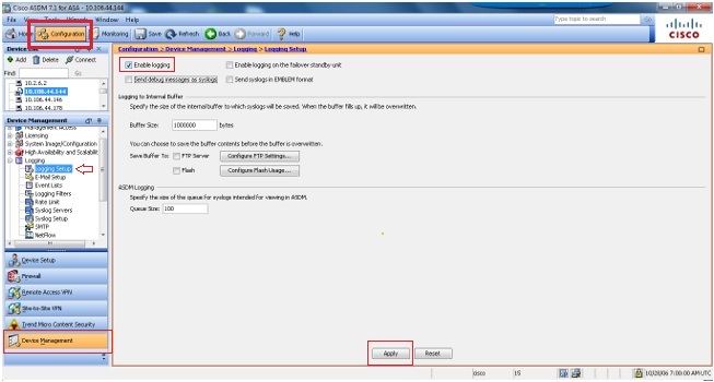
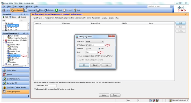
Log in to the Cisco PIX user interface, and follow the steps below to configure the PIX firewall:
Changes are applied to the assigned PIX firewall configuration files when they are generated. The configuration files are then downloaded to PIX firewalls at deployment.
|
Note: |
For every transaction happening in Cisco PIX Firewall, an ACL configured in it matches. The matched ACL along with complete transaction detail is audited through Message-ID 106100. Ensure that the logging is enabled for 'Message-ID 106100' in Cisco PIX Firewall. For more information about the message ID follow the below link. http://www.cisco.com/en/US/docs/security/pix/pix63/system/message/pixemsgs.html#wp1086617 This message identifier contains the information about both accepted and denied transactions. The log information is parsed to get the 'Used' rules and is available in the 'Firewall Rules Report > Top Used Rules Report'. |
Using CLI Console:
To enable the SNMP Manager running in Firewall Analyzer to make queries to SNMP Agent running in the firewall:
| configure terminal snmp-server host <interface name> <hostname |IP address of Firewall Analyzer> |
If you want to create a new SNMP community use the below command:
| configure terminal snmp-server community <community-string> |
Example:
| configure terminal snmp-server community public |
enable mode
configure terminal]
logging enable
logging timestamp
logging trap informational
logging device-id {context-name | hostname | ipaddress interface_name | string text}
logging host interface_name syslog_ip [udp/<syslog_port>
inspect http
Enabling HTTP inspection will generate syslogs with ID 304001. This ID will be used by Firewall Analyzer to generate URL Reports.
interface_name |
is the interface on the ASA Firewall whose logs need to be analyzed (for example: "inside" or "outside"). |
syslog_ip |
is the IP address of the syslog server (i.e. Firewall Analyzer), to which the Firewall should send the Syslogs. |
udp/<syslog_port> |
indicates that logs will be sent using the UDP protocol, to the configured syslog port on the syslog server. If left blank, logs will be sent to the default UDP port 514. |
hostname |
firewall's host name (defined with the hostname configuration command) |
ipaddress interface_name |
the IP address of a specific firewall interface named interface_name (for example: "inside" or "outside") |
string text |
an arbitrary text string (up to 16 characters) |
context-name |
in PIX 7.x or FWSM 2.x operating in multiple-context mode, the name of the firewall context can also be sent. |
For more information, refer the Cisco PIX documentation.


Refer the links for Security event syslog IDs and VPN event syslog IDs to be enabled.
Disable Logging
You can disable specific syslog IDs based on your requirement.
|
Note: |
By selecting the check mark for the Include timestamp in syslogs option, you can add the date and time that they were generated as a field to the syslogs. |
For more information, refer the Cisco PIX documentation.
Firewall Analyzer requires syslog message IDs 722030 and 722031, which by default is at debug level, to process Cisco SVC VPN logs. Set the information level to these syslog IDs by executing below commands in global configuration mode:
hostname(config)# logging message 722030 level 6 |
You can confirm by executing the below command:
hostname(config)# show logging message 722030 |
Firewall Analyzer support NetFlow version 9 packets, which is introduced in Cisco ASA 8.2.1/ASDM 6.2.1.
Configuring ASA device using console mode to send NetFlow version 9 packets to Firewall Analyzer is given below:
To disable Syslog and enable NetFlow execute the following commands:
(config)# flow-export destination inside <Firewall Analyzer Server IP> 1514
(config)# flow-export template timeout-rate 1
(config)# flow-export delay flow-create 60
(config)# logging flow-export-syslogs disable ---> This command will disable logging syslog messages
(config)# access-list netflow-export extended permit ip any any
(config)# class-map netflow-export-class
(config-cmap)#match access-list netflow-export
Associate global policy map with netflow class map
If you have a global policy map, associate the above netflow class-map netflow-export-class to the global policy.
For example: if your global policy map is named global_policy_asa, you need to execute the below commands:
(config)# policy-map global_policy_asa
(config-pmap)# class netflow-export-class
(config-pmap-c)# flow-export event-type any destination <Firewall Analyzer Server IP>if the above command fails use the below:
(config-pmap-c)# flow-export event-type all destination <Firewall Analyzer Server IP>
If you wish to create a new policy map named netflow-export-policy and make this as your global policy follow the below steps:
(config)# policy-map netflow-export-policy
(config-pmap)# class netflow-export-class
(config-pmap-c)# flow-export event-type any destination <Firewall Analyzer Server IP>if the above command fails use the one below:
(config-pmap-c)# flow-export event-type all destination <Firewall Analyzer Server IP>Make policy map netflow-export-policy as your global policy:
(config)# service-policy netflow-export-policy global
For UI mode configuration using ASDM access, refer the Cisco forum topic: https://supportforums.cisco.com/docs/DOC-6114
To disable NetFlow on Cisco ASA/ADM execute the following commands:
(config)# flow-export disable
(config)# no flow-export destination inside <Firewall Analyzer Server IP> 1514
To disable NetFlow on Cisco ASA/ADM using ASDM
|
Note: |
if you have configured Version9 Netflow logs, only Traffic reports are supported. |
Using CLI Console:
To enable the SNMP Manager running in Firewall Analyzer to make queries to SNMP Agent running in the firewall:
| configure terminal snmp-server enable snmp-server host <interface name> <hostname | IP address of Firewall Analyzer> [poll] |
Example:
| configure terminal snmp-server enable snmp-server host inside 192.168.101.155 poll |
If you want to create a new SNMP community use the below command:
| configure terminal snmp-server community <community-string> |
Example:
| configure terminal snmp-server community public |
Currently we support Cisco IOS Compatible Log Format and Original Log Format for Cisco VPN Concentrator.
Importing of already saved Cisco VPN Concentrator logs is not supported because those logs are saved in either of the following formats which is not supported in Firewall Analyzer:
Follow the below steps to configure the VPN Concentrator:
For more information, refer the Cisco VPN Concentrator documentation.
Follow the below steps to configure the Cisco IOS Switch:
Use the following command:
configure terminal
logging on
logging trap informational
logging <IP Address>
ip inspect audit-trail
For more information, refer the Cisco IOS Switch documentation.
Using Web UI:
Configure SNMP parameters for SNMP Versions 1 and 2c
Carry out the following steps:
With this, SNMP parameters for Versions 1 and 2c are configured and the changes are saved to the running configuration.
To enable the SNMP Manager running in Firewall Analyzer to make queries to SNMP Agent running in the firewall:
With this, the management station is configured and changes are saved to the running configuration.
Configure SNMP Parameters for Version 3:
SNMP Version 3 allows you to configure additional authentication and privacy options for more secure protocol operations by means of SNMP server groups and users.
Carry out the following steps:
|
Note: |
Once a user is created, you cannot change the group to which the user belongs. |
With this, SNMP parameters for Version 3 are configured, and the changes are saved to the running configuration.
Prerequisite for context/vdom in Cisco Firewalls
The Cisco Firewall IP address should be DNS resolvable from Firewall Analyzer.
There is no separate configuration required in Firewall Analyzer for receiving logs from Virtual Firewalls of the Cisco physical device.
|
Note: |
Configuration in Cisco device for Virtual Firewall |
Enable the below log IDs in Cisco device to get Security Breach reports.
| Event Type |
Log IDs |
| Deny events | 106001, 106006, 106007, 106002, 106014, 106015, 106018, 106023, 304002, 710003, 605004, 710005, 420001, 420002, 420003 |
| Virus | 338006, 338204, 338008, 338005, 338203, 338007 |
| Attack | 400000-400050, 106016, 106017, 106021, 106022, 201003, 407002, 209003, 405001 |
| Rule | 106100 |
Enable the following syslog IDs based on your VPN connection type to get VPN reports
| VPN Connection Type |
Log IDs |
| Point 2 Point | 603104, 603105, 603106, 603107, 603108, 603109, 603110 |
| IPSEC | 602303, 602304, 602305, 602306, 734001 |
| Misc | 109005, 109006, 113004, 113005, 113014, 113015, 113016, 113017 |
| Web VPN | 716001, 716002, 716038, 716039, 716055, 716056, 716057, 716058, 716059, 721016, 721018 |
| Any Connect | 113031, 113032, 113035, 113039, 751005, 751020 |
| VPN Client | 611101, 611102, 611103 |
| Other VPN events | 113019, 713228, 722030, 722031, 722051 |
|
Note: |
Ensure the logging level for the above syslog IDs are set to Informational. |
Thank you for your feedback!