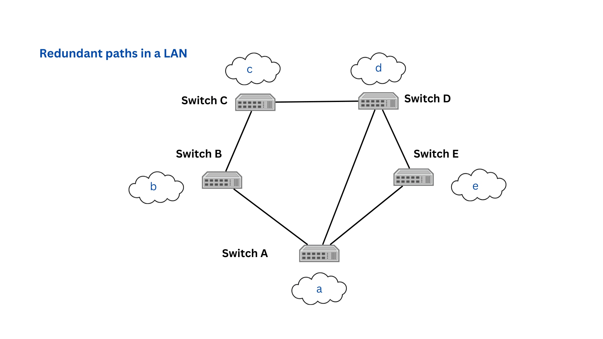
Spanning Tree Protocol (STP) is used in network switches to prevent looping and broadcast storms. In a local area network (LAN), two or more redundant paths may connect to the same network segment. When the switches or bridges transmit frames out of all available ports, these frames start to loop within the network, causing congestion. STP prevents this from happening.
Spanning Tree Protocol was developed in 1985 and has since been developed into different types suitable for various network environments. STP is a common feature in most of today's network switches.
Popular versions of STP include:
Network redundancies are provided for network segments as an insurance against unavailability. In a typical LAN, network devices like desktops, printers, and workstations are grouped into a network segment. A bridge or a switch connects each segment to another switch or router to provide internet access. Switches also connect with each other to provide intra-LAN communication. Devices communicate using Ethernet frames within the LAN.
When one of the switches is down or gets blocked, that entire segment loses connectivity. To prevent this, redundant bridges or switches are provided as a backup. When the primary is down, the secondary still maintains network connectivity.

Switches usually transmit frames out of all available ports. Without redundancies, data frames travel from the source switch, through a series of switches, until they reach the destination switch that connects to the right network segment. The destination switch then directs them to the right device. However, when redundancies exist, there is more than one way to reach the destination. The frame gets re-transmitted by both switches and starts to loop within the network.
This can spiral out of control, and before you know it, the entire network is flooded with frames. Network capacity is reached, and devices are unable to handle all the incoming traffic. This unsavory situation is known as a broadcast storm. Broadcast storms are an inherent vulnerability within a redundant LAN.
The Spanning Tree Protocol solves the issue of broadcast storms. Switching loops only arise when the switches are transmitting out all the frames at all times. STP provides the means to block certain ports at the right time, leaving only one path between the source and the destination.
To understand how STP works, we must first look at a couple of terminologies associated with it.
Root bridge or root switch: The root bridge, also known as a root switch, is identified by STP switches on their own. You can also manually assign a root bridge by assigning the lowest bridge ID number in the network, although this may affect performance. The root bridge is roughly in the center of the network and all other switches. Once the root bridge is assigned, all switches in the network find the best path to the root bridge and all other ports are blocked. Bridges do this by communicating using BDPU frames.
BPDU: A Bridge Protocol Data Unit (BPDU) is a frame used by STP-enabled switches to map different paths within a network. BPDUs also allow the root switches to control the state of other switch ports. BPDUs are exchanged between switches during boot up, and also regularly after boot up, to keep track of topology changes.
STP table: Switches calculate the cost of each path in a network and record them in the STP table. When STP is first enabled, switches send BPDUs to locate each other and record their data in the table. Subsequent topology changes are updated in the table. STP tables use costs to calculate the best paths to a particular destination.
Cost of a path: Path cost is calculated using network link speed and the available bandwidth. When the switches first map their environments, they calculate the cost for different pathways that link them to the root switch. Each switch adds its cost to the cost of the switch that comes before, until it reaches the root switch. Then the root switch selects the path with the lowest cost.
STP algorithm: Cost calculations are done by the STP algorithm. Generally, cost is calculated with the formula: network speed divided by bandwidth. Different versions of this formula are used to reflect differing speeds and network configurations.
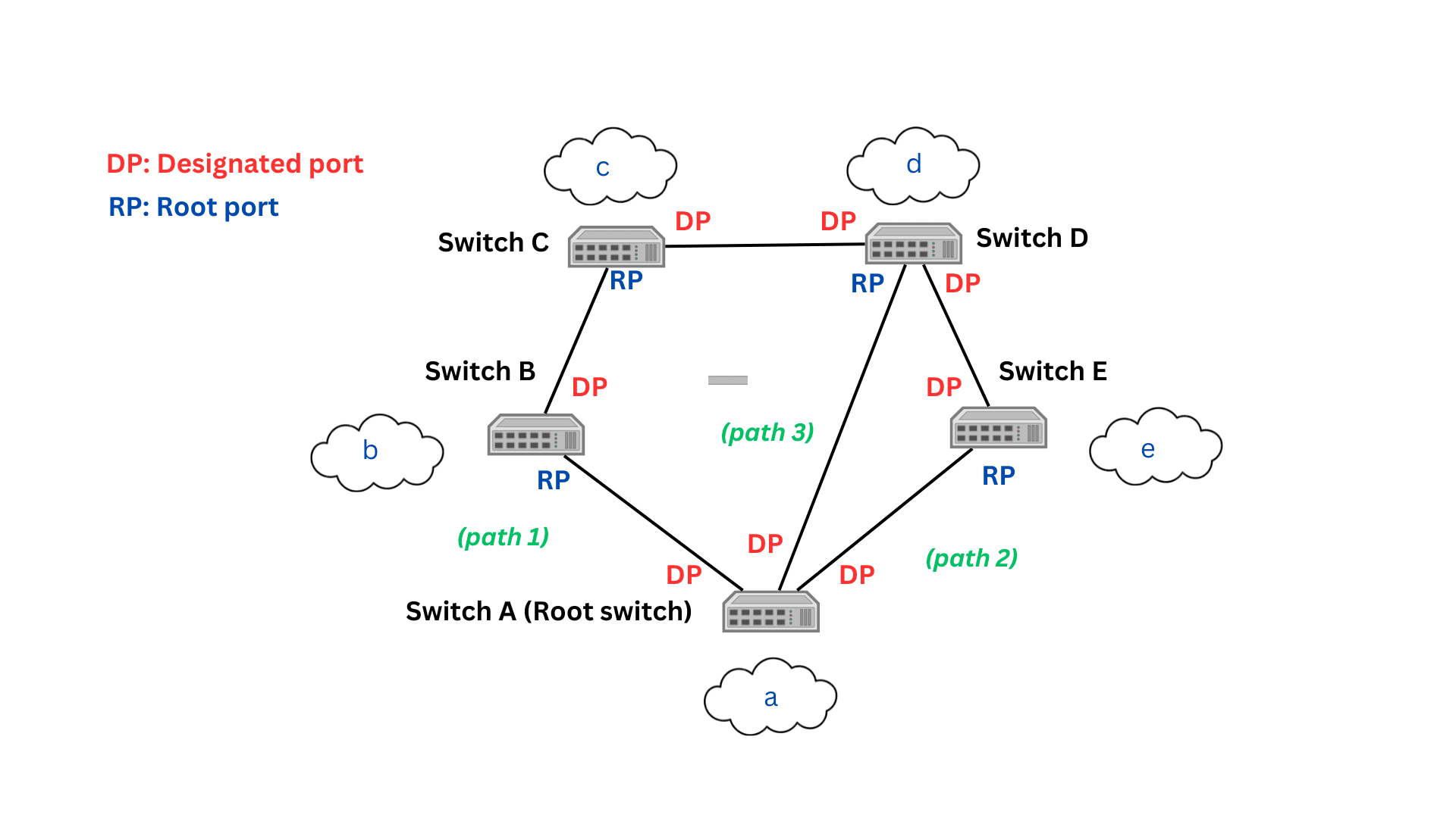
Root port:> Root ports are specified for all the switches in a network. Root ports are either ports that connect directly to the root switch or that connect to another switch in the lowest cost path to the root switch.
Designated port: In contrast, designated ports, or forwarding ports, are ports that point away from the root port. All ports in the root switch are designated ports, as it has no root ports. Switches assign root ports and designated ports during boot up.
Initially, the switches in the network would have one root port and many designated ports connecting them to other switches. The root switch uses the STP algorithm to calculate the least-cost path from the source switch to the destination switch. The designated port for this path forwards frames, while all other designated frames are put in the blocked state and don't transmit data. This means that at any time, only one path is used to send and receive frames, effectively preventing switching loops.

As illustrated in the image given above, if a device in the network segment a has to communicate with a device in the network segment c, the data frame must get to switch C from switch A (root switch). There are three possible paths. Path 1 involves switches A and B. Path 2 involves switches A, E, and D. Path 3 involves switches A and D. Using STP, we calculate that path 3 is the least-cost path. All designated ports except for the ports involved in path 3 is blocked, and the frame is transmitted through path 3.
If path 3, however, becomes congested or blocked, the next least-cost path, path 1, is selected to carry out the transmission. Redundancy is achieved. Generally, switch ports have multiple states that lie between their blocked state and forwarding state.
When switches boot up, their ports go through several port states before being assigned as designated ports or forwarding ports.
Disabled port state: The port doesn't take part in forwarding operations at all in this state. Admins can manually disable STP ports.
Blocked port state: The port doesn't participate in frame forwarding, as it is in a redundant path that could cause switching loops. The port continues to listen to BPDUs and can be transitioned to other states depending on the BPDUs.
Listening state: In the listening state, the port continues to receive and process BPDUs, and if needed, can switch to the blocked state or learning state. It does not update the table nor forward data frames.
Learning state: > In this state, the port receives BPDUs and processes them to update the STP table with the addresses of the other switches. The port continues to not participate in frame forwarding.
Forwarding state: The port receives frames from the network segments and from other ports and forwards them to the required switch. In the forwarding state, the port is fully participating in LAN switching operations. The port also continues to receive BPDUs and updating the STP table.
It takes around 15-20 seconds for the ports to move through all the states to reach the forwarding state. The STP balances the blocked and forwarding ports to prevent switching loops while still enabling redundancy.
While the original STP protocol-enabled devices took over 30 seconds to respond to topology changes, subsequent versions like Rapid Spanning Tree Protocol (RSTP) could do this in two seconds.
Similarly, Per-VLAN Spanning Tree (PVST) is an STP for VLANs. It creates a separate spanning tree for each VLAN. Similarly, Cisco published a proprietary version of the Rapid Spanning Tree Protocol (RSTP), known as Rapid Per-VLAN Spanning Tree (RPVST). Another protocol used is the Multiple Spanning Tree Protocol (MSTP).
While alternatives to STP like shortest path bridging does exist, STP continues to be popular in most network switches. Monitoring STP switches and ports is therefore a necessary practice for all organizations.
ManageEngine OpManager is a server, network, and virtualization monitoring tool that helps network admins keep track of device performance metrics and anomalies. OpManager has a special emphasis on monitoring switches, including STP monitoring. You can view the status of all STP ports in a device combined with information like priority, path cost, port state, designated root, cost of the root path, and more.
Such comprehensive information allows you to spot errors, misconfigurations, and outages in your switches and fix them proactively. OpManager also has a switch port mapper tool that shows you the state of each port in a map. OpManager can monitor other switch properties including performance of switch components like CPU and memory, switch availability, as well as traffic data.
OpManager also offers comprehensive monitoring for other network devices like servers, routers, desktops, workstations, printers, and more. With its advanced fault identification and resolution features, you can reduce the MTTR for network issues effortlessly. Download OpManager, or try our free, 30-day trial to see it for yourself!